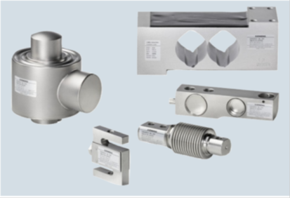
지멘스는 2가지 로드셀 시리즈를 제공합니다.
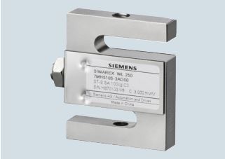
SIWAREX R 과 SIWAREX WL200. 두 시리즈 모두 스트레인 게이지를 장착하였습니다. 정적 혹은 동적 중량 측정에 사용됩니다.

SIWAREX 사의 로드셀은 산업용 계량에서 모든 어플리케이션에 적합하도록 합니다.
예로 컨테이너 & 호퍼 스케일, 플랫폼 스케일, 트럭 스케일, 하이브리드 스케일 등등.
모든 제품은 국제 법정 계량기구(EN 45501 과 OIML R601)의 ClassIII 등급의 사용이 승인되었습니다.
당사 제품은 정격 이외의 용량이나 좀더 높은 정밀도, 방폭 제품의 공급이 가능합니다.
서로 다른 시리즈가 정격하중 3kg 부터 280t까지를 커버합니다.
다양한 모듈과 특징은 다음과 같습니다.
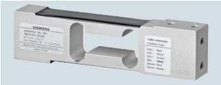
The load cell is suitable for small platform scales with one load cell (max. platform size 400 x 400 mm (15.75 x 15.75 inch)) as well as for use in medium accuracy weighing machines of Class III with a max. scale verification intervals n max= 3000d.
The measuring element is hermetically encapsulated and has a calibrated output current.
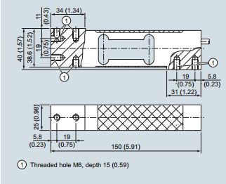
Load cell SIWAREX WL 260 SP-S AA, dimensions in mm (inch)
| Possible applications |
• Platform scales |
|
|---|---|---|
| Type |
Platform load cel |
|
| Loads | Rated load Emax |
• 3kg (6.61lb) |
| Min. initial loading Emax | 0%Emax | |
| Max. working load Lu | 150 %Emax | |
| Break load Ld | 300 %Emax | |
| Max. lateral load Llq | 100 %Emax | |
| Measurement characteristic values | Rated measuring path hn at Emax | <0.6mm |
| Rated characteristic value Cn | 2.0±0.2mV/V | |
| Tolerance D0 of zero signal | <±2%Cn | |
| Max. scale interval nIc | 3000 | |
| Min. scale interval Vmin
• Emax= 3, 5, 10 kg (6.61, 11.02, 22.05 lb) |
Emax/12 000 |
|
| Combined error Fcomb | ±0.02%Cn | |
| Deviation Fv | ±0.017%Cn | |
| Creepage error Fcr 30 min | ±0.02%Cn | |
| Electrical characteristic values | Recommended reference voltage Uref | DC 5 … 12 V |
| Input resistance Re | 409Ω±6Ω | |
| Output resistance Ra | 350Ω±3Ω | |
| Insulation resistance Ris | 5000MΩat 50 V DC | |
| Temperature coefficient
• Zero signal TKo |
0.017 %Cn/5 K |
|
| Connection and ambient conditions | Sensor material (DIN) | Aluminum |
| Max. tightening torque of fixing screws | 15 ... 20 Nm | |
| Function
• EXC + (supply +) • EXC – (supply -) • SIG + (measured signal +) • SIG – (measured signal -) • Sense + (sensor line +) • Sense - (sensor line -) • Shield |
Red |
|
| Rated temperature range Btn | -10 ... +40 °C (14 ... 104 °F) | |
| Operating temperature range Btu | -35 ... +65 °C (-31 ... +149 °F) | |
| Storage temperature range Bts | -35 ... +65 °C (-31 ... +149 °F) | |
| Degree of protection to DIN EN 60529; IEC 60529 | IP65 | |
| Connection and ambient conditions | Sensor material (DIN) | Aluminum |
| Accuracy class according to OIML R60 | C3 |
| Load cell type WL260 SP-S AA | Legal-for-trade according to OIML R60 to 3 000d, connection cable 3 m (9.84 ft) | D0 0 |
|---|---|---|
| Rated load |
•3kg (6.61lb) |
1 K |

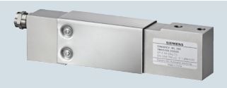
The load cell is suitable for small to medium platform scales with one load cell (max. platform size 600 x 600 mm (23.62 x 23.62 inch)) as well as for use in medium accuracy weighing machines of Class III with a max. verification interval nmax=3 000d.
The measuring element is hermetically encapsulated and has a calibrated output current.

Load cell SIWAREX WL 260 SP-S AB, dimensions in mm (inch)
| Possible applications |
• Platform scales |
|
|---|---|---|
| Type | Platform load cell | |
| Rated Loads Emax. |
•50kg (110.23lb) |
|
| Min. initial loading Emax | 0%Emax | |
| Max. working load Lu | 150 %Emax | |
| Break load Ld | 300 %Emax | |
| Max. lateral load Llq | 100 %Emax | |
| Measurement characteristic values | Rated measuring path hn at Emax | <1.22mm (0.05inch) |
| Rated characteristic value Cn | 2.0±0.2mV/V | |
| Tolerance D0 of zero signal | <±2%Cn | |
| Max. scale interval nIc | 3000 | |
| Min. scale interval Vmin | Emax/10 000 | |
| Combined error Fcomb | ±0.02%Cn | |
| Deviation Fv | ±0.017%Cn | |
| Creepage error Fcr 30 min | ±0.02%Cn | |
| Temperature coefficient
• Zero signal TKo |
0.017 %Cn/5 K 0.014 %Cn/5 K |
|
| Electrical characteristic values | Recommended reference voltage Uref | DC 5 … 12 V |
| Input resistance Re | 409Ω±6Ω | |
| Output resistance Ra | 350Ω±3Ω | |
| Insulation resistance Ris | 5000MΩat 50 V DC | |
| Connection and ambient conditions | Sensor material (DIN) | Aluminum |
| Max. tightening torque of fixing screws | 35 ... 40 Nm | |
| Rated temperature range Btn | -10 ... +40 °C (14 ... 104 °F) | |
| Operating temperature range Btu | -35 ... +65 °C (-31 ... +149 °F) | |
| Storage temperature range Bts | -35 ... +65 °C (-31 ... +149 °F) | |
| Degree of protection to DIN EN 60529; IEC 60529 | IP65 | |
| Connection cable | Function • EXC + (supply +) • EXC – (supply -) • SIG + (measured signal +) • SIG – (measured signal -) • Sense + (sensor line +) • Sense - (sensor line -) • Shield |
Color Red Black Green White Blue brown Transparent |
| Certificates and approvals | Accuracy class according to OIML R60 | C3 |
| Load cell type WL260 SP-S AB | Connecting cable 3 m (9.84 ft) | D0 0 |
|---|---|---|
| Rated load | •50kg (110.23lb) •75kg (165.35lb) • 100 kg (220.46 lb) • 150 kg (330.69 lb) • 200 kg (440.92 lb) • 300 kg (661.37 lb) • 500 kg (1 102.31 lb) |
2 P 2 S 3 A 3 E 3 G 3 K 3 P |
The load cell is suitable for small to medium platform scales with
one load cell (max. platform size 400 x 400 mm) as well as for
use in medium accuracy weighing machines of Class III with a
max. scale interval number nmax= 3 000d.
It is made of stainless steel and therefore also suitable for use in
harsh environments.
The measuring element is hermetically encapsulated and has a calibrated output current.
Load cell SIWAREX WL 260 SP-S SA, dimensions in mm (inch)
| Possible applications |
• Platform scales |
|
|---|---|---|
| Type | Platform load cell | |
| Loads | Rated load Emax. |
• 5 kg (11.02 lb) |
| Min. initial loading Emax | 0%Emax | |
| Max. working load Lu | 150 %Emax | |
| Break load Ld | 300 %Emax | |
| Max. lateral load Llq | 100 %Emax | |
| Measurement characteristic values | Rated measuring path hn at Emax | 0.27 ± 0.05 mm (0.01 ± 0.002 inch) |
| Rated characteristic value Cn | 2.0±0.2mV/V | |
| Tolerance D0 of zero signal | <±1.0%Cn | |
| Max. scale interval nIc | 3000 | |
| Min. scale interval Vmin | Emax/9 000 | |
| Combined error Fcomb | ±0.02%Cn | |
| Deviation Fv | ±0.017%Cn | |
| Creepage error Fcr 30 min | ±0.02%Cn | |
| Temperature coefficient
• Zero signal TKo |
0.017 %Cn/5 K 0.014 %Cn/5 K |
|
| Electrical characteristic values | Recommended reference voltage Uref | DC 5 … 12 V |
| Input resistance Re | 383Ω±6Ω | |
| Output resistance Ra | 351Ω±3Ω | |
| Insulation resistance Ris | 5000MΩat 50 V DC | |
| Connection and ambient conditions | Sensor material (DIN) | Stainless steel |
| Max. torque fixing screws •Emax= 3, 5, 10, 20, 50, 100 kg (6.61, 11.02, 22.05, 44.09, 110.23, 220.46 lb) •Emax= 200 kg (440.92 lb) |
14Nm 16Nm |
|
| Rated temperature range Btn | -10 ... +40 °C (14 ... 104 °F) | |
| Operating temperature range Btu | -35 ... +65 °C (-31 ... +149 °F) | |
| Storage temperature range Bts | -40 … +70 °C (-40 ... +158 °F) | |
| Degree of protection to DIN EN 60529; IEC 60529 | IP67 | |
| Connection cable | Function • EXC + (supply +) • EXC – (supply -) • SIG + (measured signal +) • SIG – (measured signal -) • Sense + (sensor line +) • Sense - (sensor line -) • Shield |
Color Green Black White Red Blue Yellow Transparent |
| Certificates and approvals | Accuracy class according to OIML R60 | C3 |
| Load cell type WL260 SP-S SA | Legal-for-trade according to OIML R60 to 3 000d, connection cable 3 m (9.84 ft) | D0 0 |
|---|---|---|
| Rated load | • 5 kg (11.02 lb) • 10 kg (22.05 lb) • 20 kg (44.09 lb) •50kg (110.23lb) • 100 kg (220.46 lb) • 200 kg (440.92 lb) |
1 P 2 A 2 G 2 P 3 A 3 G |

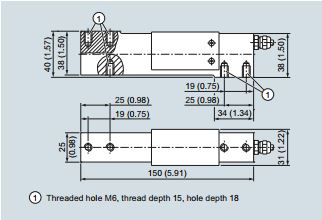
The platform load cell SIWAREX WL260 SP-S SB is excellently suited for use in platform scales with dimensions up to and including 350 x 350 mm (13.78 x 13.78 inch). It is approved for use in Class III commercial scales with maximum divisions of nmaxto 3 000d.
The measuring element is made of stainless steel, hermetically sealed and has a calibrated output current. The load cell meets the IP68 degree of protection.
SIWAREX WL260 SP-S SB, dimensions in mm (inch)
| Possible applications |
• Platform scales |
|
|---|---|---|
| Type | Platform load cell | |
| Loads | Rated load Emax. |
• 6 kg (13.23 lb) |
| Min. initial loading Emax | 0%Emax | |
| Max. working load Lu | 150 %Emax | |
| Break load Ld | 300 %Emax | |
| Max. lateral load Llq | 100 %Emax | |
| Measurement characteristic values | Rated measuring path hn at •Emax= 6 kg (13.23 lb) •Emax= 12 kg •Emax= 30 kg •Emax= 60 kg |
0.24 ± 0.02 mm (0.009 ± 0.0008 inch) (26.46 lb) 0.19 ± 0.01 mm (0.008 ± 0.0004 inch) (66.14 lb) 0.15 ± 0.01 mm (0.006 ± 0.0004 inch) (123.28 lb) 0.22 ± 0.03 mm (0.009 ± 0.0011 inch) |
| Rated characteristic value Cn | 2.0±0.2mV/V | |
| Tolerance D0 of zero signal | <±2.0%Cn | |
| Max. scale interval nIc | 3000 | |
| Min. scale interval Vmin at •Emax= 6, 12, 30, 60 kg (13.23, 26.46, 66.14, 132.28 lb) |
Emax/15 000 |
|
| Combined error Fcomb | ±0.02%Cn | |
| Deviation Fv | ±0.02%Cn | |
| Creepage error Fcr 30 min | ±0.025%Cn | |
| Temperature coefficient
• Zero signal TKo |
0.009 % Cn/10 °C 0.009 % Cn/10 °C |
|
| Electrical characteristic values | Recommended reference voltage Uref | DC 5 … 12 V |
| Input resistance Re | 400Ω±20Ω | |
| Output resistance Ra | 350Ω±3.5Ω | |
| Insulation resistance Ris | 5000MΩat 50 V DC | |
| Connection and ambient conditions | Sensor material (DIN) | Stainless steel |
| Max. tightening torque of fixing screws | 10Nm | |
| Rated temperature range Btn | -10 ... +40 °C (14 ... 104 °F) | |
| Operating temperature range Btu | -35 ... +65 °C (-31 ... +149 °F) | |
| Storage temperature range Bts | -35 … +65 °C (-31 ... +149 °F) | |
| Degree of protection to DIN EN 60529; IEC 60529 | IP67 | |
| Connection cable | Function • EXC + (supply +) • EXC – (supply -) • SIG + (measured signal +) • SIG – (measured signal -) • Sense + (sensor line +) • Sense - (sensor line -) • Shield |
Color Green Black White Red Blue Yellow blue Transparent |
| Certificates and approvals | Accuracy class according to OIML R60 | C3 |
| Load cell type WL260 SP-S SB | Legal-for-trade according to OIML R60 to 3 000d, connection cable 6 m (19.69 ft) | D0 0 |
|---|---|---|
| Rated load |
• 6 kg (13.23 lb) |
1 Q |
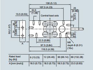
The platform load cell SIWAREX WL260 SP-S SC is excellently
suited for use in platform scales with dimensions up to and including 800 x 800 mm (31.50 x 31.50 inches). It is approved for
use in Class III commercial scales with maximum divisions of
nmaxto 4 000d. An C4 MR variant with a Y = 40 000 is available
for high-precision applications.
The use of stainless steel and the IP68/IP69K high degree protection make the SIWAREX WL260 SP-S SC highly suitable for
use in the food, beverages and tobacco industries or pharmaceutical industry.
The measuring element is made of stainless steel, hermetically sealed and has a calibrated output current.

SIWAREX WL260 SP-S SC (10 … 50 kg (22.05 … 110.23 lb), dimensions in mm (inch)
SIWAREX WL260 SP-S SC (100 … 500 kg (220.46 … 1 102.31 lb), dimensions in mm (inch)
| Possible applications |
• Platform scales |
|
|---|---|---|
| Type | Platform load cell | |
| Loads | Rated load Emax. |
•10kg (22.05lb) |
| Min. initial loading Emax | 0%Emax | |
| Max. working load Lu | 150 %Emax | |
| Break load Ld | 300 %Emax | |
| Max. lateral load Llq | 100 %Emax | |
| Measurement characteristic values | Rated measuring path hn at •10kg (22.05lb) •20kg (44.09lb) • 50 kg (110.23 lb) • 100 kg (220.46 lb) • 200 kg (440.92 lb) • 300 kg (661.39 lb) • 400 kg (881.85 lb) • 500 kg (1 102.31 lb) |
0.03 mm (0.001 inch) 0.08 mm (0.003 inch) 0.15 mm (0.006 inch) 0.12 mm (0.005 inch) 0.15 mm (0.006 inch) 0.18 mm (0.007 inch) 0.17 mm (0.007 inch) 0.19 mm (0.008 inch) |
| Rated characteristic value Cn | 2.0±0.2mV/V | |
| Tolerance D0 of zero signal | <±2.0%Cn | |
| Max. scale interval nIc | 3000 | |
| Min. scale interval Vmin at •Emax= 10, 20, 50, 100, 200, 300, 400, 500 kg (22.05, 44.09, 110.23, 220.46, 440.92, 661.39, 881.85, 1 102.31 lb) •Emax= 10, 20, 50 kg (22.05, 44.09, 110.23 lb) |
C3: Emax/10 000 C3 MR: Emax/20 000 C4 MR: Emax/40 000 |
|
| Combined error Fcomb | ±0.02%Cn | |
| Deviation Fv | ±0.02%Cn | |
| Creepage error Fcr 30 min | ±0.025%Cn | |
| Temperature coefficient
• Zero signal TKo |
0.014 % Cn/10 °C 0.01 % Cn/10 °C |
|
| Electrical characteristic values | Recommended reference voltage Uref | DC 5 … 12 V |
| Input resistance Re at • 10, 20, 50 kg (22.05, 44.09, 110.23 lb) • 100, 200, 300, 400, 500 kg (220.46, 440.92, 661.39, 881.85, 1 102.31 lb) |
380Ω±15Ω 350Ω±3.5Ω |
|
| Output resistance Ra | 350Ω±3.5Ω | |
| Insulation resistance Ris | 5000MΩat 50 V DC | |
| Connection and ambient conditions | Sensor material (DIN) | Stainless steel |
| Max. tightening torque of fixing screws • 10, 20, 50 kg (22.05, 44.09, 110.23 lb) • 100, 200, 300, 400, 500 kg (220.46, 440.92, 661.39, 881.85, 1 102.31 lb) |
10 Nm 20 Nm |
|
| Rated temperature range Btn | -10 ... +40 °C (14 ... 104 °F) | |
| Operating temperature range Btu | -35 ... +65 °C (-31 ... +149 °F) | |
| Storage temperature range Bts | -35 … +65 °C (-31 ... +149 °F) | |
| Degree of protection to DIN EN 60529; IEC 60529 | IP68, IP69K | |
| Connection cable | Function • EXC + (supply +) • EXC – (supply -) • SIG + (measured signal +) • SIG – (measured signal -) • Sense + (sensor line +) • Sense - (sensor line -) • Shield |
Color Red Black Green White Blue Yellow Transparent |
| Certificates and approvals | Accuracy class according to OIML R60 | C3 |
| Load cell type WL260 SP-S SC | Legal-for-trade according to OIML R60 to 3 000d, connection cable 3 m (9.84 ft) | 0 |
|---|---|---|
| Rated load |
• 10 kg (22.05 lb) |
2 AD0 |
| C3 MR | Legal-for-trade according to OIML R60 to 3 000d andVmin= Emax/20 000 | D5 |
| C4 MR | Legal-for-trade according to OIML R60 to 4 000d and Vmin= Emax/40 000; only for Emax= 10, 20, 50 kg (22.05, 44.09, 110.23 lb) | E5 |
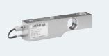
The load cell is ideal for use in tank weighing, hybrid scales or
suspended container weighing. It is made of stainless steel and
therefore also suitable for use in harsh environments.
The SIWAREX WL250 ST-S SA load cell is usable for pulling
forces and pressure forces. The preferred measuring direction is
pulling, i.e the load cell is calibrated ex factory for that direction.
When employing the load cell to measure pressure the rated values and error limits stated in the technical specifications cannot
be guaranteed.
The measuring element is hermetically encapsulated and has a calibrated output current.
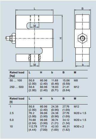
Load cell SIWAREX WL 250 ST-S SA, dimensions in mm (inch)
| Possible applications |
• Tension and pressure applications |
|
|---|---|---|
| Type | S-Type | |
| Loads | Rated load Emax. |
•50kg (110.23lb) |
| Min. initial loading Emax | 0%Emax | |
| Max. working load Lu | 150 %Emax | |
| Break load Ld | 300 %Emax | |
| Max. lateral load Llq | 100 %Emax | |
| Measurement characteristic values | Rated measuring path hn at Emax •Emax= 50, 100 kg (110.23, 220.46 lb) •Emax= 250, 500 kg (551.16, 1 102.31 lb) •Emax= 1 t (0.98 tn. L.) •Emax= 2.5, 5 t (2.46, 4.92 tn. L.) •Emax= 10 t (9.84 tn. L.) Rated characteristic value Cn Tolerance D0 of zero signal Max. scale interval nIc Min. scale interval Vmin •Emax= 50, 100 kg (110.23, 220.46 lb) •Emax= 0.25, 0.5, 1.2.5 t (0.25, 0.49, 0.98, 2.46 tn. L.) •Emax= 5, 10 t (4.92, 9.84 tn. L.) Combined error Fcomb Deviation Fv Creepage error Fcr •30min Temperature coefficient • Zero signal TKo • Characteristic value TKc |
0.18 mm (0.01 inch) 0.24 mm (0.01 inch) 0.37 mm (0.01 inch) 0.8 mm (0.03 inch) 0.57 mm (0.02 inch) 3.0 ± 0.008 mV/V <±1.0%Cn 3000 Emax/7 000 Emax/10 000 Emax/12 000 ±0.02% Cn ±0.02%Cn ±0.02%Cn 0.017 %Cn/5 K 0.014 %Cn/5 K |
| Electrical characteristic values | Recommended reference voltage Uref | DC 5 … 12 V |
| Input resistance Re | 430Ω±4Ω |
|
| Output resistance Ra | 350Ω±3.5Ω | |
| Insulation resistance Ris | 5000MΩat 50 V DC | |
| Connection and ambient conditions | Sensor material (DIN) | Stainless steel |
| Max. tightening torque of fixing screws •Emax= 3, 5, 10, 20, 50, 100 kg (6.61, 11.02, 22.05, 44.09, 110.23, 220.46 lb) •Emax= 200 kg (440.92 lb) |
14 Nm 16 Nm |
|
| Rated temperature range Btn | -10 ... +40 °C (14 ... 104 °F) | |
| Operating temperature range Btu | -35 ... +65 °C (-31 ... +149 °F) | |
| Storage temperature range Bts | -35 … +65 °C (-31 ... +149 °F) | |
| Degree of protection to DIN EN 60529; IEC 60529 | IP67 | |
| Connection cable | Function • EXC + (supply +) • EXC – (supply -) • SIG + (measured signal +) • SIG – (measured signal -) • Shield |
Color Red Black Green White Transparent |
| Certificates and approvals | Accuracy class according to OIML R60 | C3 |
| Load cell type WL260 SP-S SC | Legal-for-trade according to OIML R60 to 3 000d, connection cable 6 m (19.69 ft) | D0 |
|---|---|---|
| Rated load |
• 50 kg (110.23 lb) |
2 P |
| Explosion protection | Withou | 0 |
| Explosion protection for zones 0, 1, 2, 20, 21, 22 | 1 |

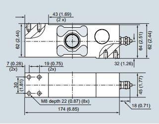
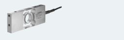
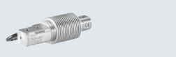
The bending beam load cell is particularly suitable for use in small-scale container and platform scales.
The measuring element is a double bending beam made of
stainless steel to which 4 strain gauges are applied.
The strain gauges are arranged so that two are stretched and
two are compressed.
Under the influence of the load acting in the measuring direction,
the spring bodies and therefore the friction-locked strain gauges
are elastically deformed. This generates a measuring signal voltage that is proportional to the load.
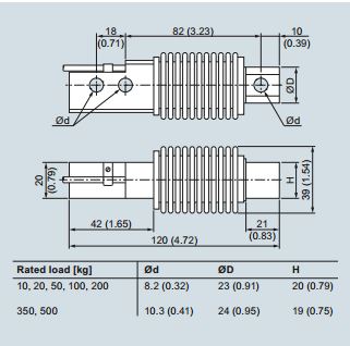
Load cell SIWAREX WL230 BB-S SA, dimensions in mm (inch)
| Possible applications |
• Container scales |
|
|---|---|---|
| Type | Bending beam load cell | |
| Loads | Rated load Emax. |
• 10 kg (22.05 lb) |
| Min. initial loading Emax | 0%Emax | |
| Max. working load Lu | 150 %Emax | |
| Break load Ld | 300 %Emax | |
| Max. lateral load Llq | 100 %Emax | |
| Measurement characteristic values | Rated measuring path hn at Emax | 0.3 mm (0.01 inch) |
| Rated characteristic valueCn | 2.0 ± 0.02 % mV/V | |
| Tolerance DOof zero signal | <±1.0%Cn | |
| Max. scale interval nLC | 3000 | |
| Min. scale interval Vmin | Emax/15 000 | |
| Minimum application range Rmin(LC) | 20 % | |
| Combined error Fcomb | ≤0.02 %Cn | |
| Deviation Fv | ≤0.017 %Cn | |
| Creepage error Fcr •30min Temperature coefficient • Zero signal TKo • Characteristic value TKc |
≤±0.02%Cn ≤±0.017%Cn/5 K ≤±0.014%Cn/5 K |
|
| Electrical characteristic values | Recommended reference voltage Uref | DC 5 … 12 V |
| Input resistance Re | 460Ω±50Ω |
|
| Output resistance Ra | 350Ω±3.5Ω | |
| Insulation resistance Ris | 5000MΩat 50 V DC | |
| SC current calibration | Standard | |
| Connection and ambient conditions | Sensor material (DIN) | Stainless steel |
| Max. tightening torque of fixing screws •Emax= 10, 20, 50.100, 200 kg (22.05, 44.09, 110.23, 220.46, 440.92 lb) •Emax= 350, 500 kg (771.62, 1 102.31 lb) |
23 Nm 70 Nm |
|
| Connection cable | Function • EXC + (supply +) • EXC – (supply -) • SIG + (measured signal +) • SIG – (measured signal -) • Shield |
Color Red Black Green White Transparent |
| Rated temperature range Btn | -10 ... +40 °C (14 ... 104 °F) | |
| Operating temperature range Btu | -35 ... +65 °C (-31 ... +149 °F) | |
| Storage temperature range Bts | -35 … +65 °C (-31 ... +149 °F) | |
| Degree of protection to DIN EN 60529; IEC 60529 | IP68 | |
| Certificates and approvals | Accuracy class according to OIML R60 | C3 |
| Load cell type WL230 BB-S SA | Legal-for-trade according to OIML R60 to 3 000d, connection cable 3 m (9.84 ft) | D0 |
|---|---|---|
| Rated load |
• 10 kg (22.05 lb) |
2 A |
| Explosion protection | Withou | 0 |
| Explosion protection for zones 0, 1, 2, 20, 21, 22 | 1 |
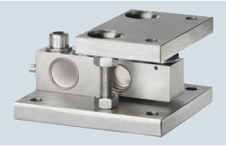
The self-aligning compact mounting unit for SIWAREX WL230 SB-S SA load cells is particularly suitable for implementation in container, platform and roller table scales
The compact mounting unit comprises a base plate and a top
plate, a self-aligning bolt and two countersunk screws.
The top plate is aligned and fixed above the base plate with the
two countersunk screws. This results in a stable unit. The height
of the top plate is adjusted so that it is three millimeters above
the installation height with load cell.
In this state the compact mounting unit serves as an installation
aid and can be used as a dummy for light installation jobs.
Prior to installation, the load cell is inserted with the self-aligning
bolt into the compact mounting unit. Then the complete unit is installed in the scales. As the result, the load bearing implement
and the mounting units are aligned. The load cells are not yet
loaded.
Finally the load bearing implement is lowered by undoing two
hex nuts under the top plate. The weight now rests on the load
cells.
In this state the load cell and the pressure pieces together form
a self-centering unit. The compact mounting unit permits sideways displacement of the top plate, and hence of the load bearing implement, by up to three millimeters.
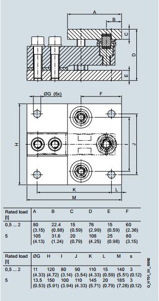
Compact mounting unit for load cells SIWAREX WL230 SB-S SA, dimensions in mm (inch)
| Rated load | 0.5, 1, 2 t (0.49, 0.98, 1.97 tn. L) | 5 t (4.92 tn. L) |
|---|---|---|
| Maximum lateral deflection with load cell | ± 3 mm (0.12 inch) | ± 3 mm (0.12 inch) |
| Lifting path of top plate | 3 mm (0.12 inch) | 3 mm (0.12 inch) |
| Return force per mm lateral deflection of top plate, in percent of load applied to load cell | 13 %/mm | 10 %/mm |
| Permissible support load with anchored top plate | 25 kN | 35 kN |
| Permissible lifting force at top plate | 25 kN | 50 kN |
| Permissible lateral force at top plate when top plate is anchored | 3 kN | 5 kN |
| Compact mounting unit | For load cells of series SIWAREX WL230 SB-S SA Material: Stainless steelFor load cells with a rated load of: | D0 |
|---|---|---|
|
• 500 kg (1 102.31 lb), 1 t (0.98 tn. L.) • 2 t (1.97 tn. L.) • 5 t (4.92 tn. L.) |
A G P |
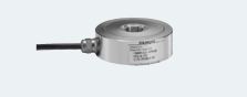
The compression load cell is particularly suitable for implementation in container, hopper and vehicle scales.
The measuring element is a solid cylinder made of stainless
steel to which 4 strain gauges are applied.
The load which acts centrally in the measuring direction causes
the spring bodies and therefore the friction-locked strain gauges
to be elastically deformed. This generates a measuring signal
voltage that is proportional to the load.
Load cell SIWAREX WL270 CP-S SA, dimensions in mm (inch)
| Possible applications |
• Container scales |
|
|---|---|---|
| Type | Compression load cell | |
| Loads | Rated load Emax. |
• 2t (1.97tn.L.) |
| Min. initial loading Emax | 0%Emax | |
| Max. working load Lu | 150 %Emax | |
| Break load Ld | 300 %Emax | |
| Max. lateral load Llq | 75 %Emax | |
| Measurement characteristic values | Rated measuring path hn at Emax | 0.5 mm (0.02 inch) |
| Rated characteristic valueCn | 2.0±0.02%mV/V | |
| Tolerance DOof zero signal | ≤±1.0%Cn | |
| Max. scale interval nLC Min. scale interval Vmin |
3000 | |
| Emax= 2, 5, 10, 20, 50 t (1.97, 4.92, 9.84, 19.68, 49.21 tn. L.) | Emax/10 000 | |
| Minimum application range Rmin(LC) | 30 % | |
| Combined error Fcomb ±0.02%Cn Creepage error Fc |
±0.02%Cn | |
| •30min Temperature coefficient |
≤±0.023%Cn | |
| • Zero signal TKo | ≤±0.023%Cn/5 K | |
| • Characteristic value TKc | ≤±0.017%Cn/5 K | |
| Electrical characteristic values | Recommended reference voltage Uref | DC 5 … 12 V |
| Input resistance Re | 700Ω±7Ω | |
| Output resistance Ra | 700Ω±7Ω | |
| Insulation resistance Ris | 5000MΩat 50 V DC | |
| Connection and ambient conditions | Rated temperature range Btn | -10 ... +40 °C (14 ... 104 °F) |
| Operating temperature range Btu | -35 ... +65 °C (-31 ... +149 °F) | |
| Storage temperature range Bts | -35 … +65 °C (-31 ... +149 °F) | |
| Degree of protection to DIN EN 60529; IEC 60529 | IP68 | |
| Connection cable | Function • EXC + (supply +) • EXC - (supply -) • SIG + (measured signal +) • SIG - (measured signal -) • Shield |
Color Red Black Green White Transparent |
| Certificates and approvals | Accuracy class according to OIML R60 | C3 |
| Load cell type WL270 CP-S SA | Legal-for-trade according to OIML R60 to 3 000d, connection cable 15 m (49.21 ft) | D0 |
|---|---|---|
| Rated load |
• 2 t (1.97 tn. L.) • 5 t (4.92 tn. L.) • 10t (9.84tn.L.) • 20 t (19.68 tn. L.) • 30 t (29.63 tn. L.) • 50 t (49.21 tn. L.) |
4G 4P 5A 5G 5K 5P |
| Explosion protection | Without | 0 |
| Explosion protection for zones 0, 1, 2, 20, 21, 22 | 1 |
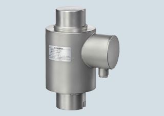
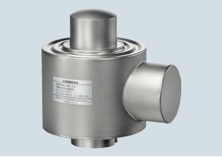
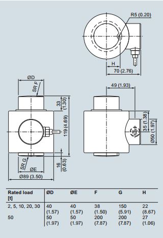
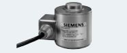
The compression load cell is particularly suitable for implementation in container, hopper and vehicle scales.
The measuring element is a solid cylinder made of stainless
steel to which 4 strain gauges are applied.
The load which acts centrally in the measuring direction causes
the spring bodies and therefore the friction-locked strain gauges
to be elastically deformed. This generates a measuring signal
voltage that is proportional to the load.
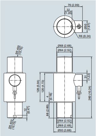
Load cell SIWAREX WL 270 CP-S SB, dimensions in mm (inch)
| Possible applications | Container scales | |
|---|---|---|
| Type | Compression load cell | |
| Loads | Rated load Emax. | 100 t (98.42 tn. L.) |
| Min. initial loading Emax | 0%Emax | |
| Max. working load Lu | 150 %Emax | |
| Break load Ld | 300 %Emax | |
| Max. lateral load Llq | 10 %Emax | |
| Measurement characteristic values | Rated measuring path hn at Emax | 0.36 mm (0.01 inch) |
| Rated characteristic valueCn | 2.0±0.02%mV/V | |
| Tolerance DOof zero signal | ≤±1.0%Cn | |
| Max. scale interval nLC Min. scale interval Vmin |
3000 | |
| Emax= 100 t (98.42 tn. L.) | Emax/9 000 | |
| Minimum application range Rmin(LC) | 33 % | |
| Combined error Fcomb | ±0.02%Cn | |
| Deviation Fv Creepage error Fcr |
≤±0.02%Cn | |
| •30min Temperature coefficient |
≤±0.023%Cn | |
| • Zero signal TKo | ≤±0.023%Cn/5 K | |
| • Characteristic value TKc | ≤±0.017%Cn/5 K | |
| Electrical characteristic values | Recommended reference voltage Uref | DC 5 … 12 V |
| Input resistance Re | 700Ω±7Ω | |
| Output resistance Ra | 700Ω±7Ω | |
| Insulation resistance Ris | 5000MΩat 50 V DC | |
| Connection and ambient conditions | Sensor material (DIN) | Stainless steel |
| Rated temperature range Btn | -10 ... +40 °C (14 ... 104 °F) | |
| Operating temperature range Btu | -35 ... +65 °C (-31 ... +149 °F) | |
| Storage temperature range Bts | -35 … +65 °C (-31 ... +149 °F) | |
| Degree of protection to DIN EN 60529; IEC 60529 | IP68 | |
| Connection cable | Function • EXC + (supply +) • EXC - (supply -) • SIG + (measured signal +) • SIG - (measured signal -) • Sense + (sensor line +) • Sense – (sensor line -) • Shield |
Color Green Black White Red Yellow Blue Transparent |
| Certificates and approvals | Accuracy class according to OIML R60 | C3 |
| Load cell type WL270 CP-S SB | Legal-for-trade according to OIML R60 to 3 000d, connection cable 20 m (65.62 ft) | D0 |
|---|---|---|
| Rated load | 100 t (98.42 tn. L.) | 6A |
| Explosion protection | Without | 0 |
| Explosion protection for zones 0, 1, 2, 20, 21, 22 | 1 |
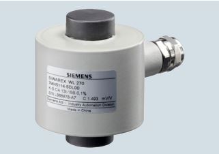
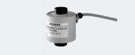
The compression force load cell is particularly suitable for use in container and bin weighing equipment.
The measuring element is a cylinder made of stainless steel to
which 4 strain gauges are applied.
The load which acts centrally in the measuring direction elastically deforms the spring body and thus the force-fitted strain
gauges. This generates a measuring signal voltage that is proportional to the load. The load cell's rated measuring path depends on the rated load and is between 0.23 and 3.11 mm
(0.01 and 0.12 inch).
An enclosure made from painted steel protects the strain gauge
from environmental influences. The load cell is fitted with a heatresistant cable as standard.
Heavy load versions with a rated load of 350 and 500 t (344.47 and 492.10 tn. L.) are available for extreme requirements.
A high-temperature range option is available for all
SIWAREX WL270 K load cells. Specially developed strain
gauges are deployed here. They can be used in temperatures
ranging from -30 °C to 250 °C (-22 °F to 482 °F) without being
damaged. Accuracy is only minimally affected.
Cables and accessory parts are also specially adapted to suit
this extended temperature range.
In especially sensitive applications such as cranes, enhanced
safety is required. This is also true of measurement plants. Using
double bridges in load cells achieves the equivalent of a redundant configuration. Both measuring bridges supply consistent
measured values. If one bridge fails, the other takes over.
These options can be ordered for load classes from 13 t
(12.79 tn. L.). Double bridge and high temperature options can
also be ordered together.
| Possible applications | • Container scales • Bin weighing equipment |
|
|---|---|---|
| Type | Compression load cell | |
| Loads | Rated load Emax. | • 2.8 t (2.76 tn. L.) •6t (5.91tn.L.) • 13 t (12.79 tn. L.) • 28 t (27.56 tn. L.) • 60 t (59.05 tn. L.) • 130 t (127.95 tn. L.) • 280 t (275.58 tn. L.) • 350 t (344.47 tn. L.) • 500 t (492.10 tn. L.) |
| Min. initial loading Emax | 0%Emax | |
| Max. working load Lu | 120 %Emax | |
| Break load Ld | 300 %Emax | |
| Max. lateral load Llq | 10 %Emax | |
| Measurement characteristic values | Rated measuring path hn at Emax • 2.8 t (2.76 tn. L.) • 6 t (5.91 tn. L.) • 13 t (12.79 tn. L.) • 28 t (27.56 tn. L.) • 60 t (59.05 tn. L.) • 130 t (127.95 tn. L.) • 280 t (275.58 tn. L.) • 350 t (344.47 tn. L.) • 500 t (492.10 tn. L.) |
0.23 mm (0.009 inch) 0.38 mm (0.015 inch) 0.54 mm (0.02 inch) 0.82 mm (0.03 inch) 1.19 mm (0.05 inch) 1.81 mm (0.07 inch) 2.66 mm (0.10 inch) 2.73 mm (0.11 inch) 3.11 mm (0.12 inch) |
| Rated characteristic valueCn | 1.5 mV/V | |
| Tolerance DOof zero signal | ≤±1.5%Cn | |
| Tolerance Dcof characteristic value | ±0.5% | |
| Combined error Fcomb | ≤±0.1% | |
| Deviation Fv Creepage error Fcr |
≤±0.1% | |
| •30min Temperature coefficient |
≤±0.06% | |
| • Zero signal TKo | ≤±0.25%Cn/5 K | |
| • Characteristic value TKc | ≤±0.25%Cn/5 K | |
| Electrical characteristic values | Recommended reference voltage Uref | DC 6 … 12 V |
| Supply voltage Usr(reference value) | 6V | |
| Input resistance Re • 2.8, 6, 13, 28, 60, 130, 280 t (2.76, 5.91, 12.79, 27.56, 59.05, 127.95, 275.58 tn. L.) • 350, 500 t (344.47, 492.10 tn. L.) |
275Ω±50Ω 450Ω±4.5Ω |
|
| Output resistance Ra • 2.8, 6, 13, 28, 60, 130, 280 t (2.76, 5.91, 12.79, 27.56, 59.05, 127.95, 275.58 tn. L.) • 350, 500 t (344.47, 492.10 tn. L.) |
245Ω±0.2Ω 480Ω±4.8Ω |
|
| Insulation resistance Ris | 5000MΩ | |
| Connection and ambient conditions | Sensor material (DIN) | Steel, painted |
| Rated temperature range Btn | -10 ... +60 °C (14 ... 140 °F) | |
| Operating temperature range Btu | -20 ... +70 °C (-4 ... +158 °F) | |
| Storage temperature range Bts | -30...+80°C (-22...+176°F) | |
| Degree of protection to DIN EN 60529; IEC 60529 | IP66 | |
| Accuracy class | 0.1 % | |
| Connection cable | Function • EXC + (supply +) • EXC - (supply -) • SIG + (measured signal +) • SIG - (measured signal -) • Shield Transparent |
Color Red White Black Blue Transparent |
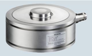
The ring torsion load cell is particularly suitable for use in container, conveyor, platform and roller table scales.
The measurement element is a ring torsion spring made of stainless steel. Two strain-gage spirals (DMS) are applied to the upper and lower faces of the ring respectively. The spring element
is deformed by the load acting centrically in the measurement
direction. This compresses the strain-gage of the upper face of
the ring and extends the strain-gage on the lower face of the
ring. This causes a change in the electrical resistance of the
force-locked strain-gage, which is detected by means of a
bridge circuit.
All load cells with a rated load of up to 13 t are equipped with an
integral overload protection
| Possible applications |
• Container scales • Conveyor scales • Platform scales • Roller table scales |
|||
|---|---|---|---|---|
| Type | Ring-torsion load cell | |||
| Loads | Rated load Emax. | • 60kg (132.28lb) • 130 kg (286.60 lb) • 280 kg (617.29 lb) |
• 0.5 t (0.49 tn. L.) • 1 t (0.98 tn. L.) • 2 t (1.97 tn. L.) • 3.5 t (3.45 tn. L.) • 5 t (4.92 tn. L.) • 10 t (9.84 tn. L.) |
• 13 t (12.80 tn. L.) • 28 t (27.56 tn. L.) • 60 t (59.05 tn. L.) |
| Min. initial loading Emax | 0%Emax | 0%Emax | 0%Emax | |
| Max. working load Lu | 200 %Emax | 150 %Emax | 150 %Emax | |
| Break load Ld | 500 %Emax | 300 %Emax | 300 %Emax | |
| Max. lateral load Llq | 75 %Emax | 100 %Emax | 75 %Emax | |
| Measurement characteristic values | Rated measuring path hn at Emax | 0.07 mm (0.003 inch) | 0.1±0.02mm (0.04±0.0008inch) |
0.11 … 0.2 mm |
| Rated characteristic valueCn | 1 mV/V | 2 mV/V | 2 mV/V | |
| Tolerance DOof zero signal | ≤±1.0%Cn | ≤±1.0%Cn | ≤±1.0%Cn | |
| Max. scale interval nLC | 3000 | 3000 | 3000 | |
| Min. load cell verification intervals Vmin | Emax/16 000 | Emax/17 000 | Emax/17 000 | |
| Combined error Fcomb | ≤±0.02%Cn | ≤±0.02%Cn | ≤±0.02%Cn | |
| Deviation Fv | ≤±0.01%Cn | ≤±0.01%Cn | ≤±0.01%Cn | |
| Return of zero signal | ≤±0.0167%Cn | ≤±0.0167%Cn | ≤±0.0167%Cn | |
| Creepage error Fcr • 30min • 20…30min |
≤±0.0245%Cn ≤±0.0053%Cn |
≤±0.0245%Cn ≤±0.0053%Cn |
≤±0.0245%Cn ≤±0.0053%Cn |
|
| Temperature coefficient • Zero signal TKo • Characteristic value TKc |
≤±0.004%Cn/5K ≤±0.004%Cn/5K |
≤±0.004%Cn/5K ≤±0.004%Cn/5K |
≤±0.004%Cn/5K ≤±0.004%Cn/5K |
≤±0.004%Cn/5K ≤±0.004%Cn/5K |
| Design | Platform | Bending beam |
|---|---|---|
| Possible applications |
Small platform scales Small conveyor scales |
Container, conveyor and platform scales |
| Series | SP | BB |
| Pictures |
|
|
| Rated load Emax | • 6 kg (13.23 lb) • 12 kg (26.46 lb) |
• 10 kg (22.05 lb) • 20 kg (44.09 lb) • 50kg (110.23lb) • 100 kg (220.46 lb) • 200 kg (440.92 lb) • 350 kg (771.72 lb) |
| Accuracy class | C3 | C3 |
| Max. load cell verification interval (nIC) | 3000 | 3000 |
| Min. load cell verification interval (Vmin) | Emax/12 000 | Emax/15 000 |
| Supply voltage (Usr) | 5 ... 15 V | 5 ... 15 V |
| Rated characteristic value | 2 mV/V | 2 mV/V |
| Degree of protection | IP66/IP68 | IP66/IP68 |
| Material | Stainless steel | Stainless steel |
| Ex protection according to ATEX (optional) | II 2 G EEx ib IIC T6/T4 II 3 G EEx nA/nL IIC T6/T4 II1D/2D/3DT70°C (158°F) |
II 2 G EEx ib IIC T6/T4 II3G EExnA/nLIICT6/T4 II 1D/2D/3D T 70 °C (158 °F) |
| Mounting units | • Base plate with overload protection • Elastomer bearings • Combination mounting units |
| Design | Shear beam |
|---|---|
| Possible applications | Container, conveyor, overhead rail and platform scales |
| Series | SB |
| Pictures |
|
| Accuracy class | C3 |
| Max. load cell verification interval (nIC) | 3000 |
| Min. load cell verification interval (Vmin) | Emax/10 000 |
| Supply voltage (Usr) | 5 ... 18 V |
| Rated characteristic value | 2 mV/V |
| Degree of protection | IP66/IP68 |
| Material | Stainless steel |
| Ex protection according to ATEX (optional) | II 2 G EEx ib IIC T6/T4 II 3 G, EEx nA/nL IIC T6/T4, II1D/2D/3DT70°C (158°F) |
| Mounting units | • Base plate with overload protection • Elastomer bearings • Combination mounting units • Guide element for combination mounting units |
| Design | Bending ring | ||
|---|---|---|---|
| Possible applications | Container, conveyor, overhead rail and platform scales | ||
| Series | RN | ||
| Pictures |
|
||
| Rated load Emax |
• 60 kg (132.28 lb) • 130 kg (286.60 lb) • 280 kg (617.29 lb) |
• 500 kg (1 102.31 lb) • 1 t (0.98 tn. L.) • 2 t (1.97 tn. L.) • 3.5 t (3.45 tn. L.) • 5 t (4.92 tn. L.) • 10 t (9.84 tn. L.) |
• 13 t (12.80 tn. L.) • 28 t (27.56 tn. L.) • 60 t (59.05 tn. L.) |
| Accuracy class | C3 | ||
| Max. load cell verification interval (nIC) | 3000 | ||
| Min. load cell verification interval (Vmin) | Emax/17 500 | Emax/10 000 | Emax/10 000 |
| Supply voltage (Usr) | 5 ... 30 V | ||
| Rated characteristic value | 1 mV/V | 2 mV/V | 2 mV/V |
| Degree of protection | IP66/IP68 | ||
| Material | Stainless steel | ||
| Ex protection according to ATEX (optional) | II 2 G EEx ib IIC T6/T4 II 3 G, EEx nA/nL IIC T6/T4, II1D/2D/3DT70°C (158°F) |
||
| Mounting units |
• Elastomer bearing • Combination mounting unit • Guide element for combination mounting units • Self-aligning bearings |
||
| Design | Compression cell | ||
|---|---|---|---|
| Possible applications | Container, hopper and vehicle scales | Container, hopper and vehicle scales | |
| Series | CC | K | |
| Pictures |
|
|
|
| Rated load Emax |
• 10 t (9.84 tn. L.) • 25 t (24.61 tn. L.) • 40 t (39.37 tn. L.) • 60 t (59.05 tn. L.) |
• 100 t (98.42 tn. L.) |
• 2.8 t (2.76 tn. L.) • 6 t (5.91 tn. L.) • 13 t (12.80 tn. L.) • 28 t (27.56 tn. L.) • 60 t (59.05 tn. L.) • 130 t (127.95 tn. L.) • 280 t (275.58 tn. L.) |
| Accuracy class | C3 | C1 | 0.1 % |
| Max. load cell verification interval (nIC) | 3000 | 1000 | - |
| Min. load cell verification interval (Vmin) | Emax/12 500 | Emax/10 000 | - |
| Supply voltage (Usr) | 5 ... 25 V | 6 ... 12 V | |
| Rated characteristic value | 2 mV/V | 1.5 mV/V | |
| Degree of protection | IP66/IP68 | IP65 | |
| Material | Stainless steel | Steel, painted | |
| Ex protection according to ATEX (optional) | II 2 G EEx ib IIC T6/T4 II 3 G EEx nA/nL IIC T6/T4 II 1D/2D/3D T 70 II 2 G EEx ib IIC T6/T4 II 3 G EEx nA /nL IIC T6/T4, II 1D / 2D / 3D T 70°C (158 °F) |
||
| Mounting units |
• Combination mounting units • Self-aligning bearings |
• Self-aligning bearings | • Self-aligning bearings |

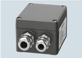
The aluminum JB junction box is required for parallel connection
of load cells. A maximum of 4 load cells can be connected in
parallel in one junction box.
If more than 4 load cells are to be connected, a second junction
box must be connected in parallel via a cross connection. The
junction box can be used in potentially explosive areas
(grounded, intrinsically-safe circuits).
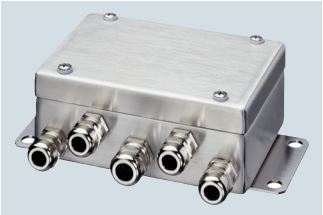
The stainless steel JB junction box is required for parallel connection of load cells. A maximum of 4 load cells can be connected in parallel in one junction box.
The extension box EB is used to lengthen the connection cable
of load cells.
Load cells can be connected using 4-wire and 6-wire systems.
The cable connection to the weighing module or to the junction
box JB must always be made using a 6-wire system. The
SIWAREX cable 7MH4 702-8AG or ...-8AF is recommended.
If load cell cables are extended to a junction box JB, the cable
glands M16 x 1.5 must be replaced. The following are required
per load cell:
• 1 EMC cable gland M20 x 1.5
• 1 extension M16 x 1.5 male thread to M20 x 1.5 female thread.
The extension box can be used in potentially explosive areas
(grounded, intrinsically-safe circuits).

The highly flexible grounding cable is used to discharge parasitic currents.
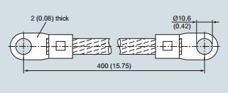
Grounding cable, dimensions in mm (inch)